

In an environment where process monitoring and control are becoming increasingly critical, and where there is a need to create visualizations to make operation easier for users, Human-Machine Interface (HMI) devices are extremely helpful in daily operations. HMIs can connect to different control devices such as PLCs using available ports and/or communication protocols.
Controllino PLCs, specifically the MAXI and MEGA models, offer the advantage of being able to connect to HMI panels using the Modbus protocol, either through their Ethernet port (TCP/IP) or through the integrated RS485 port (SN65HVD08 interface).
In a previous blog (<span style=”color:blue; text-decoration:underline;”>HMI with Controllino PLC via TCP/IP</span>), the steps to communicate a Controllino PLC with an HMI using the TCP/IP protocol were explained. In this blog, we will explain how to connect a Controllino PLC with an HMI using Modbus RTU.
Note: You must select the correct library in the Arduino IDE by navigating to Tools → Board → Controllino MINI/MAXI/MEGA. If you cannot find the required file, you may use this <span style=”color:blue; text-decoration:underline;”>link</span> to download it, as it is required before uploading the code to the PLC.
For this configuration, you will need the following:
-
1 Controllino MAXI or MEGA PLC
-
A 12/24 VDC power supply (which must be configured so that the voltage supplied to the PLC does not exceed 5 Volts, otherwise there is a risk of permanent damage)
-
The HMI panel you wish to control
-
A 3-wire male serial adapter
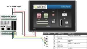
Please check the HMI panel manual for the pin assignment required to connect via RS485 to the Controllino PLC. You can view the wiring diagram with pin assignments for the MAXI and MEGA by clicking on this link and this other link.
Step 1: HMI Configuration
First, configure the HMI using the designated software according to the brand and/or product compatibility. It is recommended to use software that includes the most up-to-date versions and drivers.
Within the software, create the following analog tags: R0, D0, D1, and A0, configuring them as shown in the image below.
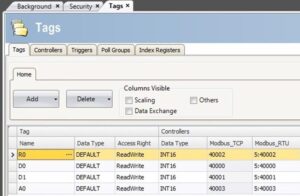
In the tags, you will notice that for RTU communication, the nodes begin with “5:”. This is because the Controllino PLC uses that number as its unit ID when operating as a Modbus slave. This value is not mandatory and can always be changed within the code that will be uploaded to the device.
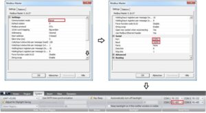
Once the tags with Modbus RTU addresses have been created, proceed to create the Modbus I/O device to connect to the Controllino MAXI or MEGA PLC. In the I/O device section of your software:
-
Create a new device
-
Define it as Serial
-
Set the station to “0” (if required)
-
Select the serial port configured as RS485 (verify in your software which port is assigned this parameter)
Step 2: Using Modbus RTU
To establish the connection, use the following code, remembering the station number assigned to the Modbus slave PLC, and upload it to the device:
#include <Controllino.h> /* Usage of the CONTROLLINO library allows you to use CONTROLLINO_xx aliases in your sketch. */
#include “ModbusRtu.h” /* Usage of ModBusRtu library allows you to implement the Modbus RTU protocol in your sketch. */
/*
CONTROLLINO – Modbus RTU protocol Slave example for MAXI and MEGA, Version 01.00
The sketch is relevant only for CONTROLLINO variants MAXI and MEGA (because of the necessity of the RS485 interface)!
This sketch is intended as an example of the communication between devices via RS485 with utilization the
ModbusRTU protocol.
In this example the CONTROLLINO is used as the Modbus slave!
For more information about the Modbus protocol visit the website: https://modbus.org/
Modbus master device can read Modbus 16 bit registers (provided by the slave):
0 – analog CONTROLLINO_A0 value (0 – 1024)
1 – digital CONTROLLINO_D0 value (0/1)
2 – Modbus messages received
3 – Modbus messages transmitted
Modbus master device can write Modbus 16 bit registers:
4 – relay CONTROLLINO_R0 (0/1)
5 – relay CONTROLLINO_R1 (0/1)
6 – relay CONTROLLINO_R2 (0/1)
7 – relay CONTROLLINO_R3 (0/1)
To easily evaluate this example you need a second CONTROLLINO as Modbus master running DemoModbusRTUMaster
Example sketch.
Please note that both CONTROLLINOs need 12/24V external supply and you need to interconnect GND, -, + signals
of RS485 screw terminal.
Modbus Master-Slave library for Arduino (ModbusRtu.h) was taken from the website:
https://github.com/smarmengol/Modbus-Master-Slave-for-Arduino
It was necessary to modify the setting of the PORTJ for pins DE and RE control. These pins are located at the
PORJ and on the pins PIN6(DE) and PIN5(RE).
IMPORTANT INFORMATION!
Please, select the proper target board in Tools->Board->Controllino MAXI/MEGA before Upload to your CONTROLLINO.
(Please, refer to https://github.com/CONTROLLINO-PLC/CONTROLLINO_Library if you do not see the CONTROLLINOs in
the Arduino IDE menu Tools->Board.)
Created 30 March 2017
by David
(Check https://github.com/CONTROLLINO-PLC/CONTROLLINO_Library for the latest CONTROLLINO related software stuff.)
*/
int D0 = CONTROLLINO_D0;
int D1 = CONTROLLINO_D1;
int R0 = CONTROLLINO_R0;
int A0_ = CONTROLLINO_A0;
// This MACRO defines a Modbus slave address.
// For any Modbus slave devices are reserved addresses in the range from 1 to 247.
// Important note only address 0 is reserved for a Modbus master device!
#define SlaveModbusAdd 5
// This MACRO defines the number of the comport that is used for the RS 485 interface.
// For MAXI and MEGA RS485 is reserved UART Serial3.
#define RS485Serial 3
// The object ControllinoModbuSlave of the class Modbus is initialized with three parameters.
// The first parameter specifies the address of the Modbus slave device.
// The second parameter specifies type of the interface used for communication between devices – in this sketch
// is used RS485.
// The third parameter can be any number. During the initialization of the object this parameter has no effect.
Modbus ControllinoModbusSlave(SlaveModbusAdd, RS485Serial, 0);
// This uint16 array specified internal registers in the Modbus slave device.
// Each Modbus device has particular internal registers that are available for the Modbus master.
// In this example sketch internal registers are defined as follows:
// (ModbusSlaveRegisters 0 – 3 read only and ModbusSlaveRegisters 4 – 7 write only from the Master perspective):
// ModbusSlaveRegisters[0] – Read an analog value from the CONTROLLINO_A0 – returns value in the range from 0 to 1023.
// ModbusSlaveRegisters[1] – Read an digital value from the CONTROLLINO_D0 – returns only the value 0 or 1.
// ModbusSlaveRegisters[2] – Read the number of incoming messages – Communication diagnostic.
// ModbusSlaveRegisters[3] – Read the number of outcoming messages – Communication diagnostic.
// ModbusSlaveRegisters[4] – Sets the Relay output CONTROLLINO_R0 – only the value 0 or 1 is accepted.
// ModbusSlaveRegisters[5] – Sets the Relay output CONTROLLINO_R1 – only the value 0 or 1 is accepted.
// ModbusSlaveRegisters[6] – Sets the Relay output CONTROLLINO_R2 – only the value 0 or 1 is accepted.
// ModbusSlaveRegisters[7] – Sets the Relay output CONTROLLINO_R3 – only the value 0 or 1 is accepted.
uint16_t ModbusSlaveRegisters[8];
// The setup function runs once when you press reset (CONTROLLINO RST button) or connect the CONTROLLINO to the PC
// In the setup function is carried out port setting and initialization of communication of the Modbus slave protocol.
void setup()
{
delay(5000);
Serial.begin(9600);
Serial.println(“Started”);
pinMode(D0, OUTPUT);
pinMode(D1, INPUT);
pinMode(R0, OUTPUT);
pinMode(A0_, INPUT);
ControllinoModbusSlave.begin( 19200 ); // Start the communication over the ModbusRTU protocol. Baud rate is set at 19200.
Serial.begin(9600);
}
// The loop function runs over and over again forever
void loop()
{
// This instance of the class Modbus checks if there are any incoming data.
// If any frame was received. This instance checks if a received frame is Ok.
// If the received frame is Ok the instance poll writes or reads corresponding values to the internal registers
// (ModbusSlaveRegisters).
// Main parameters of the instance poll are address of the internal registers and number of internal registers.
ControllinoModbusSlave.poll(ModbusSlaveRegisters, 8);
// While are not received or sent any data, the Modbus slave device periodically reads the values of analog and
// digital outputs.
// Also it updates the other values of registers.
analogWrite(D0, ModbusSlaveRegisters[0]);
digitalWrite(R0, ModbusSlaveRegisters[2]);
ModbusSlaveRegisters[1] = digitalRead(D1);
ModbusSlaveRegisters[3] = analogRead(A0_);
}
Finally, make sure that all devices are connected as shown in the wiring diagram from the first image of this blog, and perform the test.
At Logicbus, we offer extensive information to help you expand the applications in which you can use your Controllino PLCs. We will be happy to answer your questions and appreciate your attention.


sales@logicbus.com | support@logicbus.com | +1 619 616 7350 | Start conversation