

In electronics design, validation, and testing, the margin for error is shrinking. Modern embedded systems, RF circuits, and analog components operate on tighter voltage tolerances and lower power thresholds than ever before. For hardware design and test engineers, a bench power supply is more than just a utility to turn on a prototype it is a critical instrument that can mean the difference between discovering a subtle design flaw and destroying an expensive, one-of-a-kind microchip.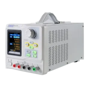
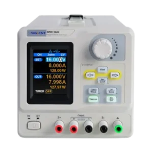
While switching power supplies dominate high-power applications due to their efficiency, linear power supplies remain the gold standard on the engineer’s bench due to their unmatched cleanliness and responsiveness. The Siglent SPD1305X Programmable Linear DC Power Supply stands out as an exemplary tool engineered to meet these rigid laboratory standards.
The Core Pillars of an Indispensable Bench Power Supply
When evaluating a bench power supply for a professional engineering environment, four fundamental pillars must be analyzed: precision, stability, protection, and ease of use.
1. Precision and Resolution
When working with low-power microcontrollers or delicate analog-to-digital converters (ADCs), variations of a few millivolts can alter sensor readings or skew power-consumption data. A professional bench supply must offer both high programming precision (setting the exact desired value) and high readback resolution (measuring what the load is actually drawing).
The Siglent SPD1305X addresses this with a 5-digit voltage and 4-digit current display, providing an operating resolution of 1 mV / 1 mA. This level of granularity allows engineers to observe minute shifts in current draw when an embedded system switches from a deep-sleep state to an active wireless transmission mode.
2. Stability, Low Ripple, and Noise
The main drawback of switching power supplies is the high-frequency switching noise injected into the device under test (DUT). Linear power supplies solve this by utilizing a heavy transformer and linear regulators to smooth the output.
Stability is measured by ripple and noise parameters. The SPD1305X features an exceptionally clean output with a ripple and noise threshold of ≤ 350 µVrms / 3 mVpp. This ultra-low electrical noise is indispensable when debugging sensitive RF circuits, audio amplifiers, or high-resolution instrumentation where ambient power supply noise could mask weak signals.
3. Comprehensive Circuit Protection
Prototyping is inherently prone to accidents, such as short circuits, miswired breadboards, or component failures. If a power supply cannot react instantly to an anomaly, a prototype can easily overheat or catch fire.
Essential protection mechanisms include:
-
Over-Voltage Protection (OVP): Instantly cuts the output if the voltage exceeds a user-defined limit, protecting downstream ICs from overvoltage stress.
-
Over-Current Protection (OCP): Limits or shuts off current if a short circuit occurs, stopping thermal runaway before components melt.
4. Ease of Use and Real-Time Visualization
Modern testing workflows demand intuitive interfaces. Instead of relying purely on static digital readouts, engineers benefit heavily from visual tracking. The SPD1305X features a 2.8-inch true-color TFT-LCD screen that displays voltage and current waveforms in real time. Seeing a graphical trend of current draw over time allows engineers to spot transient spikes without needing to hook up an external oscilloscope.
Siglent SPD1305X: Technical Breakdown 
The Siglent SPD1305X unifies these four pillars into a compact, programmable, single-channel instrument. Below is a summary of its core hardware specifications:
| Feature | Specification |
| Output Style | Single-Channel Linear DC |
| Voltage Range | 0 to 30 V |
| Current Range | 0 to 5 A |
| Total Max Power | 150 W |
| Setting/Readback Resolution | 1 mV / 1 mA |
| Ripple & Noise (Voltage) | ≤ 350 µVrms / 3 mVpp |
| Transient Response Time | < 50 µs (50% to 100% load change) |
| Connectivity Ports | USB Device, LAN (Supports SCPI Commands) |
Essential Applications for Design and Test Engineers
The unique combination of high precision and clean linear output makes the SPD1305X a versatile asset across multiple engineering domains.
Low-Power Embedded System Validation
Engineers designing Internet of Things (IoT) devices face the challenge of maximizing battery life. These devices utilize aggressive power-saving modes, dropping their current draw to microamps before spiking back up to hundreds of milliamps during data transmission.
The fast transient response time of the SPD1305X (< 50 µs) ensures that when the DUT suddenly demands more current, the supply recovers its voltage level almost instantly, preventing brownout resets. The real-time waveform display allows engineers to visually correlate software execution states with physical power consumption.
Component Testing and Stress Analysis
During the design phase, hardware engineers must test components at their operational boundaries (low voltage, maximum current, voltage drops). The programmable nature of the SPD1305X allows users to save up to five groups of timing setup configurations. Engineers can program custom voltage steps, ramps, or automated cycles directly from the front panel or via PC software, simulating unstable battery conditions or power grid fluctuations to ensure product resilience.
Automated Test Equipment (ATE) Integration
In production testing or automated hardware-in-the-loop (HIL) environments, manual adjustments are inefficient. Because the SPD1305X supports standard SCPI (Standard Commands for Programmable Instruments) via USB or LAN connections, it can be seamlessly integrated into automated software routines written in LabVIEW, Python, or C#. Test scripts can automatically vary the input voltage to a product under test, log the current draw, and verify pass/fail criteria over thousands of iterations without human intervention.
Advanced Feature Spotlight: 4-Wire Remote Sense Compensation
A common headache in low-voltage, high-current testing is the voltage drop across the lead wires connecting the power supply to the DUT. Due to internal wire resistance, if a supply outputs exactly 3.300 V, the actual voltage reaching a heavy load might drop to 3.150 V, causing the system to malfunction.
[ Power Supply Output: 3.300V ] ─── (Voltage Drop across leads) ───► [ DUT Input: 3.150V ]
▲
[ Fixed by 4-Wire Remote Sense Leads ]
The Siglent SPD1305X solves this with its 4-wire Remote Sense mode. By connecting an additional pair of high-impedance sense leads directly to the power inputs of the DUT, the power supply measures the exact voltage at the target component rather than at its own terminals. It then dynamically compensates for the lead wire resistance, adjusting its output automatically to ensure that the device receives the exact programmed voltage regardless of load changes or cable length.
Conclusion & Engineering Value
A reliable bench power supply is an investment in data integrity and hardware safety. The Siglent SPD1305X represents a balanced synthesis of linear performance, clean power, and programmable flexibility. For design engineers building the next generation of embedded hardware or test engineers deploying automated validation racks, having a supply that delivers 1 mV resolution, under 350 µVrms noise, and a 4-wire remote sense mechanism is the definitive way to eliminate power anomalies from your troubleshooting equations.


sales@logicbus.com | support@logicbus.com | +1 619 616 7350 | Start conversation