Pressure sensors with display, often also called screen pressure switches, are widespread today: on the one hand, they allow electronic pressure measurement with a continuous analogue output signal.
On the other hand, they have two freely configurable switching outputs that can be modified directly on site by means of a visualization. This advantage materializes when the control with the display of all the parameters of the installation is far from the measuring point.
This is often the case in water treatment facilities or in tank fill level monitoring. In this type of process, pressure is measured directly at different points in the installation, for example, in tanks, pumps, valves, filters, etc.
However, the control of the installation is located in another part of the building and if it is necessary to open or close valves due to breakdowns or operation, it must be done on site. This forces us to require updated and reliable information from our installation at all times and in real time.
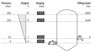
Since pressure switches with a display usually only show the pressure being measured on site, Trafag pressure sensors give us more functions:
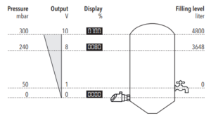
Indication value in percentage.
If there is a different nominal pressure in different places due to the installation, the operator must know to which measuring point each value belongs. This is often impractical and error-prone. It is best if you simply display the measured value in percentage at each measurement point.
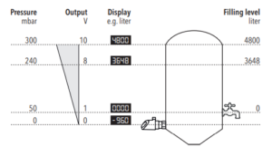
User-defined indication value.
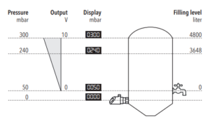
In some cases you may not want to simply show the percentage of the measurement interval, but you want to see a more quantitative value such as liters. With the Trafag pressure transmitter and pressure switch, the indication heat can be parameterized: both the lower and upper final values can be entered as any other value.
Scalable and movable measuring range.
If now the output signal should not emit the lower limit value, but we seek to set it to zero, a parameterization of the measurement range must be performed. For this purpose, the lower endpoint of the measuring range can be increased by up to 50% of the measurement range through additional functionality. In the case of the image, it is placed at 50mbar to have a custom measurement range.
Note: The remaining measuring range must consist of at least 50% of the original range.
Adaptation of the output signal.
Some standard output signals have a lower final value of 0V. However, this makes it impossible to detect a conductor break. The output signals can therefore be adapted independently of the adjusted measuring range: in this way an output signal from 0-10 Vdc to 0.1- 10.1Vdc can be parameterized. With this we will achieve that false contacts or breakage of conductors are detected more easily.
Many more possibilities: simple parameterization via Android application.
These numerous adjustment possibilities can be made both with the on-screen keys and with the Android app via the NFC interface. In the synoptic menu of the application, parameterization can be carried out in a simple and controlled way.
In addition, pre-saved parameter sets can be loaded into the sensor directly from the smartphone app. This considerably simplifies parameterization and makes shifting more secure.
You can also reset all parameterization settings using a factory reset and start the setup process all over again.
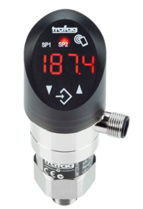
Recommended pressure sensors:
Visit our website:
www.logicbus.com


sales@logicbus.com | support@logicbus.com | +1 619 616 7350 | Start conversation

