

Human-Machine Interface (HMI) devices allow us to control and monitor processes by providing clear visualization for users. Different control devices, such as PLCs, can be connected to them using the available ports and/or through a communication protocol. Controllino PLCs, in their MAXI and MEGA models, offer the advantage of being connected to HMI panels using the Modbus protocol, either through their Ethernet port (TCP/IP) or via the integrated RS485 port (SN65HVD08 interface).
In this blog, we will explain how to connect a Controllino PLC to an HMI using Modbus TCP/IP (Note: you must select the correct library by navigating in the Arduino IDE menu to Tools → Board → Controllino MINI/MAXI/MEGA. If you cannot find the required file, you can use the provided link to download it, as it is necessary before uploading the code to the PLC).
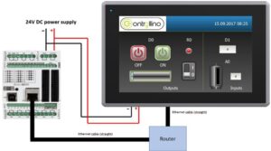
For this configuration, you will need: one Controllino MAXI or MEGA PLC, a 12/24 VDC power supply (which must be configured so that the voltage supplied to the PLC does not exceed 5 volts, otherwise there is a risk of permanently damaging the equipment), the HMI panel you want to control, two Ethernet cables, and one router.
Step 1: HMI Configuration
First, configure the HMI using the software designated according to the brand and/or product compatibility. It is recommended to use a version that includes the most up-to-date drivers and software releases. Within the software, create the analog tags R0, D0, D1, and A0, configuring them as shown in the image below:
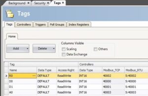
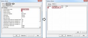
Once the tags with Modbus TCP addresses have been created, we will create the Modbus I/O device to connect to the Controllino MAXI or MEGA PLC. In the I/O device section of the software, create a new device, define it as Ethernet type, then set the station to “0” (if required), and finally enter the IP address assigned to the PLC. If you do not know this address, you can use the guide provided and upload the code to the Serial Monitor so it displays the corresponding IP address.
Step 2: Using ModbusRTU
To establish the connection, you must first load the Modbus TCP libraries from the provided link. Simply download the file, unzip the folder, and save it in Arduino > Libraries. Once you have the PLC’s IP address, modify it in the following code and upload it to the device:
#include <Controllino.h>
#include <SPI.h>
#include <Ethernet.h>
#include “Mudbus.h”
Mudbus Mb;
int D0 = CONTROLLINO_D0;
int D1 = CONTROLLINO_D1;
int R0 = CONTROLLINO_R0;
int A0_ = CONTROLLINO_A0;
// Function codes 1 (read coils), 3 (read registers), 5 (write coil), 6 (write register)
// signed int Mb.R[0 to 125] and bool Mb.C[0 to 128] MB_N_R MB_N_C
// Port 502 (defined in Mudbus.h) MB_PORT
void setup()
{
uint8_t mac[] = { 0x00, 0xAA, 0xBB, 0xCC, 0xDE, 0x02 };
uint8_t ip[] = { 192, 168, 0, 103 }; // CHANGE this to the IP address of your CONTROLLINO
uint8_t gateway[] = { 192, 168, 0, 254 };
uint8_t subnet[] = { 255, 255, 255, 0 };
Ethernet.begin(mac, ip, gateway, subnet);
delay(5000);
Serial.begin(9600);
Serial.println(“Started”);
pinMode(D0, OUTPUT);
pinMode(D1, INPUT);
pinMode(R0, OUTPUT);
pinMode(A0_, INPUT);
}
void loop()
{
Mb.Run();
analogWrite(D0, Mb.R[0]);
digitalWrite(R0, Mb.R[2]);
Mb.R[1] = digitalRead(D1);
Mb.R[3] = analogRead(A0_);
}
Finally, make sure that all devices are connected as shown in the diagram in the first image of this blog and perform the test.
At Logicbus, we provide extensive information to help you expand the applications in which you can use your Controllino PLCs. We will be happy to answer your questions and appreciate your attention.


sales@logicbus.com | support@logicbus.com | +1 619 616 7350 | Start conversation