
Description:
A level control sensor in a heated cooking-oil tank is used to automate the level of cooking-oil, but also to supplement the safety of equipment. If an oil tank overflows, then hot oil can be a hazard to employees. Spilled oil interrupts production and requires cleanup.
If the level of oil in a heated tank drops too low, then the oil can overcook or start a fire. In some jurisdictions it is required to have a sensor to detect low levels and shut off the fryer’s heater for safety. In some applications, if an oil tank runs empty, then pumps will run dry and burn out.
Function: 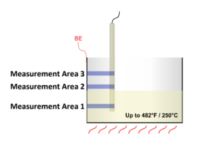
The KF-sensor is mounted vertically in a hopper and extends down into the vessel.
Area 1 – When the low signal switches, the sensor sends a signal indicating the oil level in the tank is low and to ask for more oil.
Area 2 – When the high signal switches, the sensor sends a signal indicating that the tank is full and to stop filling.
Area 3 – If the high-high signal switches, the sensor triggers an alarm. A high-high level should never be reached. An emergency shutdown of filling pumps and other equipment or employee evacuation can be performed.
The measurement area of the sensor is well defined even with material sticking to the sensor or to the container wall. Probe length and measurement areas can be customized (50mm increments).
Parts Required:
Sensor: KFS-53-15-300-15/85/130-PEEK-D16-X02-Y55 KF0563
Amplifier: KFA-5-4-XXL-P-A-KL-Y50 AF0063
Mounting Adapter: 16mm-3/4”NPT-V4A SA7004

The KF-Series will detect material in liquid or solid state while ignoring material buildup on the sensor.
Installation:
- Install the probe in your tank
- Connect the sensor to the KF-amplifier
- Connect the BE-cable!
- Connect the power supply
- Adjust the sensor
Adjustment:
The sensor is adjusted after the sensor is mounted in the tank and the tank filled to the max filling level.
The adjustment is done in this order:
- Locate the sensitivity adjustment potentiometer on the amplifier. The actual adjustment potentiometer is located under the amplifier’s faceplate. The faceplate is removed with four spring latches located in the corners of the unit.
- Fully immerse the sensor up to the top switching point (area 3) in oil after mounting the sensor in the tank.
- Reset the sensor’s sensitivity by turning the potentiometer counterclockwise 20 full turns, or until the sensor’s LED switches to green (whichever comes first).
- Adjust the sensor to the product you wish to detect by turning the potentiometer clockwise until the sensor’s LED switches to yellow.
- Add 1/4 turn for safety by turning the potentiometer a further 90 degrees clockwise.
- Repeat steps 3-6 for each switching point (channel) used.
The KF0563 sensor has 3 connectors: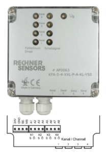
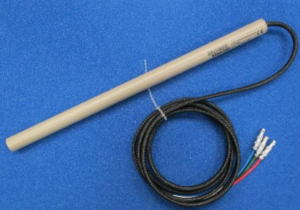
Blue = Channel 1
Red = Channel 2
Green = Channel 3


sales@logicbus.com | support@logicbus.com | +1 619 616 7350 | Start conversation