

In a high-performance vehicle, the suspension system does more than hold the car, it adapts to the vehicle’s aerodynamic forces, varying road conditions and driver actions.
In addition, the complex multi-point suspension systems in use in NASCAR® and Formula 1® require the use of models and simulations to ensure compliance under load. Important models and analyses are carried out to take these variables into account. However, the final step in maximizing performance is live testing to validate the simulation model.
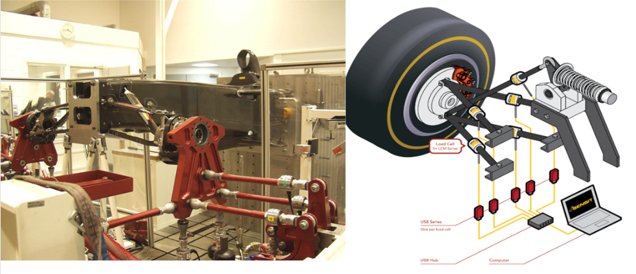
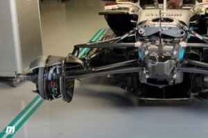
To achieve this, the load cells are placed in line with each suspension arm, providing detailed information on the load passing through each arm, accurate measurements of steering load and indirect grip of the front tires that allows the suspension system to be adjusted to optimize performance and handling.
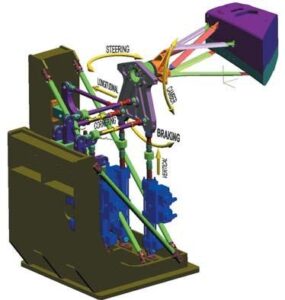
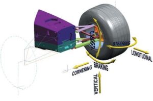
The images above show the directions in which the car’s suspension reacts to each of the forces exerted, for example: aerodynamics, braking, cornering, acceleration and rim angle. For this, the manufacturers and developers of these vehicles implement simulations in which they calculate the margin of force that occurs in a race to guarantee the safety of the driver and performance of the car on the track.
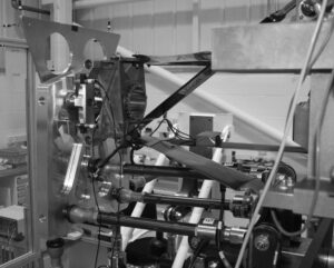
They achieve this with a bench simulation in which they use pistons that apply force parallel to the real conditions and load cells to obtain the results of these simulations with this new alloy of lightweight materials are determined for these racing vehicles.
But the simulations not only serve to calculate the forces exerted by the road conditions and determine the resistance of the new materials and designs of new suspension parts which must be as light and resistant as possible but also to calculate the force applied by the aerodynamic force in the rear and front wings since the vehicles reach speeds of 300 km / h because it is necessary to have the best stability in the car.
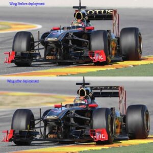
In the rear wing it carries a huge load of force since being closed is what keeps the rear wheels to the ground avoiding understeer, but when the fin is open it reduces the surface area of the rear wing and, therefore, serves to reduce aerodynamic drag, which quickly increases speed on the straight.
This is where the load cell comes into play and we can measure the force that must be exerted to lift the rear fin and also how much aerodynamic drag is being applied with the fin closed. With this data we can design with what resistance properties the fin will be manufactured or the design of the piston with which the fin will be opened and closed.

To extract real-time data, the USB220 high-resolution USB load cell digital amplifier eliminates the need for an analog amplifier, power supply and display equipment. The module receives power from the PC via a USB cable, which provides excitation voltage for the sensor and generates a high-resolution load cell. The analog output voltage of the sensor is then digitized and processed by a microprocessor using the integrated high-resolution (24-bit) analog-to-digital converter (ADC). The built-in USB transmitter and receiver allows the microprocessor to communicate with the PC via the USB link.
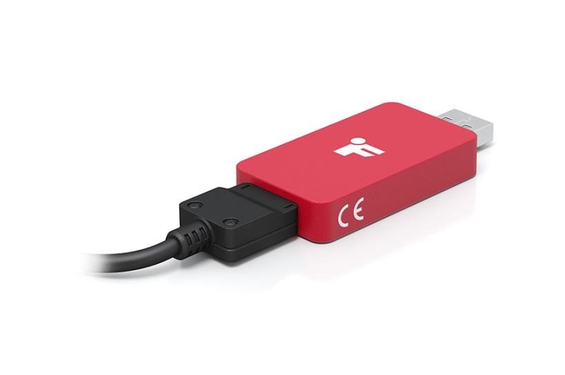
The USB load cell amplifier works hand in hand with SENSIT test and measurement software, which allows users to monitor the actual sensor output in real time. This is calculated based on the calibration values stored in the onboard memory. The simple plug-and-play connection allows you to control the output of the USB load cell interface and enjoy measurement that is less affected by noise, temperature variation and excitation. The USB220 USB Charge Cell Digital Amplifier is designed and manufactured by FUTEK in the USA.

Visit our website:
www.logicbus.com


sales@logicbus.com | support@logicbus.com | +1 619 616 7350 | Start conversation