

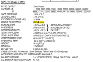
When we’re working with a load cell you could say that the first step in every installation is to verify the correct functionality and health of the sensor, but you might ask, how do I run a verification and most importantly what do these results mean?
Today we’ll be working with an LTH500 from FUTEK and a multimeter.
Internal resistance verification.
We oughta know by now, load cells are strain gauge based, meaning that they work with several internal resistances that suffer electric alterations depending on the physical change applied to the load cell. Knowing this we could measure the resistance of the input and the output so that we can know if they’re meeting the specs shown on the data sheet.
We might find a slight difference between the readings and the data sheet, but as long as it is within tolerance, we should be good to go.
It’s time to use the multimeter. First we’ll try the input resistance; usually you can find these resistance by measuring between the black and red lead wires, but it may vary depending of the brand.
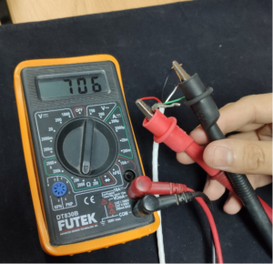
Taking into consideration the resistance tolerance, this load cell seems in good shape.

Afterwards we’ll test the output resistance by measuring between the white and green cable. As said before, colors might be different for other brands.
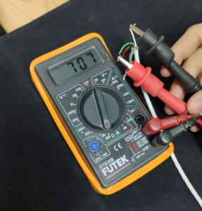
This load cell is within tolerance parameters, so it can be used properly.
If we were to have an out of specification resistance, then a new load cell would have to be acquired. Damage in the resistances of the load cell are often caused by overloads, faulty power supply, of axis forces, or extraneous loads.
Verifying zero load readings.
After verifying resistances, we have to check load cell performance. To do this we must firstly verify the zero load readout.
To run this test, we’ll need a power supply that is within specifications to energize the load cell, so that we can measure the milivoltage output.
Once we have the power supply prepared and connected to the load cell we need to measure milivoltage on the load cell signal output (in this brand white and green wires).
In the output, you should have:
Excitation voltage * Load cell sensitivity = Output readings (mV)
After running this test we got an acceptable reading of 0.03mV.
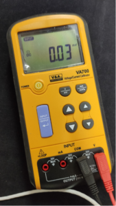
Really close to 0.
There’s several reason that might cause a zero shift on the load cell:
- Load cell nearing the end of life cycle: After a lot of cycles, mismanagement, or bad environment conditions, you might get small damages on the stain gauge that the load cell won’t be able to absorb therefore it’ll create a growing zero shift. When the load cell reaches a 10% zero shift (Based on the sensitivity value) it’s time to get a new sensor.
- Overload: When load cell capacity is exceeded by a mismanaged load, strain gauge could be over stressed and won’t be able to recover from that flexion. Therefore we’ll have a big zero shift if this is not taken care of quickly.
- Off axis and extraneous loads: When we place loads on the load cells that aren’t hitting the load cells on active parts or are applying momentum on the sensor, we’ll start to notice a lot of shift in the readouts. This is one of the most common damaging actions when working with load cells.
Tests with known weights.
Although with the previous steps we can already have a good idea of the health and status of our load cell, it is necessary to apply this test to know its performance.
If we have known weights, we can do mathematical tests with the sensitivity of the cell to know how much voltage we should expect at the sensor output. If you have a calibration or performance certificate, this case becomes easier to solve. If none of these factors are available, we can perform this with arbitrary forces and check the behavior of the cell.
For the example we use in this cell it would be a sensitivity of 2mV/V so at the output we should expect values lower than this sensitivity multiplied by the excitation.

As it can be seen, the load cell escalated correctly when we applied force gradually.
If you want more information, you can visit our blog and website.


sales@logicbus.com | support@logicbus.com | +1 619 616 7350 | Start conversation