
Current limitations of a controller board
To this day, there are many industrial control technologies available to us. Usually we can find controller boards of various types and configurations, such as microcontroller-based controller boards such as PICs or ATMega on Arduinos. Or there are also more specialized modules for high grade industrial control such as PLCs or DCS systems which are already designed for large scale automation projects.
These microcontroller-based controllers that we already know are generally designed to work in industrial processes in which several actions or instructions are being repeated cyclically and at not very high speeds. For these automation tasks microcontrollers are perfect because their architecture and configuration is designed to work that way, and their programming complexity is relatively simple.
But what happens when we have other types of applications where for example we need several processes are developing and running simultaneously and at high speeds, or for example, what if we have a project where we need to develop a specific circuit or digital system that is analyzing signals of different types at high speeds?
A microcontroller would fall short due to different limitations:
- Factory default configuration: a microcontroller internally is designed and manufactured to follow instructions cyclically and receive and send certain input and output signals. We cannot change internally how these signals and instructions are processed, we can only program when and how the instructions are processed.
- Speed limitation: Microcontrollers work in conjunction with a clock which defines the time or frequency at which signals are processed. Usually this clock is limited and is preset by the manufacturer.
- A single core configuration for processing: Clearly there are microcontrollers with more than one core, but we are also limited to the number of cores that comes from the factory, which normally microcontrollers such as ATMega or PIC only have a single core without the possibility of executing parallel and simultaneous instructions.
For applications where you need more speed and a specific configuration for various tasks, there are chips such as ASICs (Application Specific Integrated Circuit) which are designed specifically for specific tasks, such as a graphics card for graphics processing, and can be manufactured without the limitations of a microcontroller, but we still have the limitation that it is designed from the factory for a specific task without really being able to change much.
After reading this, is there really a board that we can customize to our liking over and over again and without being limited by the hardware? Well, the answer could be simply to use an FPGA chip based board.
Definition and architecture of an FPGA board
An FPGA board, or Field Programmable Gate Array, is a development board based on an FPGA chip or integrated circuit. This card has the peculiarity that it does not come configured or programmed by factory, that is to say, it comes blank so that you can create any circuit or digital system on it.
To know a little more about how it works and how we can use it, we will explain internally how it is designed. The FPGA integrated circuit is internally formed by programmable logic blocks that are interconnected with each other by connection matrices and data buses, as well as an input and output block. These programmable logic blocks consist of programmable logic gates, a flip flop unit for data storage and a multiplexer.
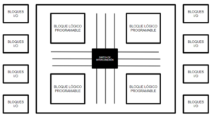
Fig. 1 Basic architecture of an FPGA card
In this Programmable Logic Block the logic operations are performed, and it could be said that all the existing logic gates are handled. We have input logic values that enter the block and output logic values resulting from the block operations. It already depends on the type of chip and the manufacturer how each logic block is configured, but generally this is the structure it handles.
Now, each FPGA chip is made up of several of these blocks linked together by interconnection matrices, or switches, which we can modify to change the path in which the data moves. That is, we can modify the path by which the input signals move throughout the FPGA chip, and thus have the ability to create a huge amount of circuits and digital logic, from logic circuits such as developing an AND gate to create a multi-core processor! IMPORTANT: in an FPGA chip, unlike a microcontroller, there is no processor in which we can program software and modify its instructions, rather in an FPGA chip we “program” its internal hardware to create digital circuits.

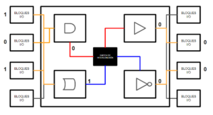
Fig. 2 Basic example of a circuit made on an FPGA board. The upper image shows a first configuration, while the lower image is the same configuration but with a different path defined by the interconnect switch.
In Figure 2 we see an example of how an FPGA chip is configured at a very basic level. We have 4 elements that come into play: The input module (left side) where we have 3 input signals with different Boolean values 1, 0 and 1, the logic blocks which are configured with 4 logic gates AND, OR, Buffer and NOT, the interconnection switch, which defines how the paths where the signals will travel are interconnected, and the output module (right side) where the results of the logic gates are displayed.
In the upper image of figure 2 we have as a result 0 and 0 in the output signals, but if we go to the lower image we see that the results are now 1 and 1, and this is because we change the signal paths through the configuration switch.
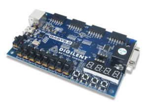
Fig. Xilinx FPGA-based development board
The logic blocks are connected by the interconnection switch which defines how these blocks are connected to each other. The point of FPGA boards is that we can modify these interconnections and create any possible digital combination to make virtually any digital circuit.
The above example was a small circuit that can be made with an FPGA board, but as I mentioned earlier we can make any digital circuit, we can even simulate an Arduino inside an FPGA board, or even make our own Dual Core microcontroller! It’s all in the development skills.
This is why an FPGA board is used for high performance and high data processing applications.
Software vs Hardware: How an FPGA board is programmed.
An FPGA board is not programmed like a microcontroller. A microcontroller has a microprocessor which is programmed with low-level or high-level software instructions to be performed, since its configuration requires software programming to function.
In an FPGA card it is different. Mainly the hardware that the board will have is “programmed” or configured, as we saw in the previous example. Basically, the internal arrangement of the hardware is described depending on the circuit or digital system that we want to create.
A development environment is mainly used to help us create the hardware description of the FPGA, and the language used is Hardware Description Language, or HDL. The most common HDLs are VHDL or Verilog.
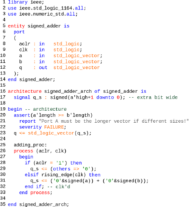
Fig. VDHL language used for programming FPGA development boards
FPGA board applications
FPGA cards are currently widely used for applications where high speed, multi-data processing or specific applications in the IoT industry are needed. The most common applications are the following:
- Signal processing in telecommunication and networking.
- Development of integrated systems in the aerospace and defense industry.
- In the development of ASICs
- Computer vision systems
There are several levels of FPGA development cards, so we can also find cards designed for academic use, in which they are used to demonstrate and explain different concepts and digital systems, as they lend themselves to create digital circuits and understand from scratch the logic of them, as for example the Basys 3 Artix-7 (Link to TV) from Digilent, where we have several buttons, switches, LEDs, displays and inputs and outputs to connect peripherals and develop basically any circuit or custom digital logic with the ability to delete the program and start from scratch which makes it perfect for testing and prototyping.
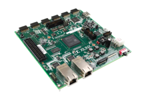
Fig. Basys 3 Artix-7 FPGA board dedicated to a basic level.
www.logicbus.com


sales@logicbus.com | support@logicbus.com | +1 619 616 7350 | Start conversation