

If you are going to communicate a Fatek P2 or P5 Series HMI with a PLC of any of the brands supported, (we have an article with the list of supported Drivers: Blog sobre Drivers inglés) The first thing you will need is the latest version of FvDesigner which is the development software for all Fatek HMIs.
Notes: To download the most recent version you can consult our Technical Support teams via email: support@logicbus.com they will provide you with a download link at no cost and even a small Demo project.
Fatek is constantly developing new equipment, so if your HMI is not in the version you have installed, surely there will already be a new version, please consult technical support. Once FvDesigner is installed and we have a project created and open, it will be necessary to define the physical medium through which it will be connected, you can consult the following article about it:
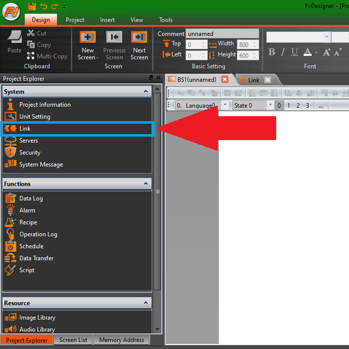
In FvDesigner to create a new communication or link, go to “Project Explorer” – “System” – “Link”; As shown in the following image, you must left click on “Link”
With this action, a window called “Link” will be displayed like the one shown below, you must click on the “Add” button to add a new communication, there are also the options “Delete” to delete a communication already created, and “Edit” to modify the configuration of a communication already created.
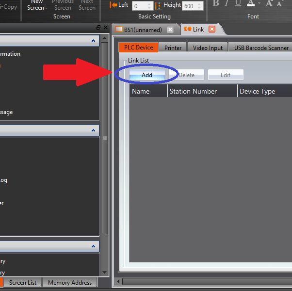
Clicking on “Add” will display the following sub window:
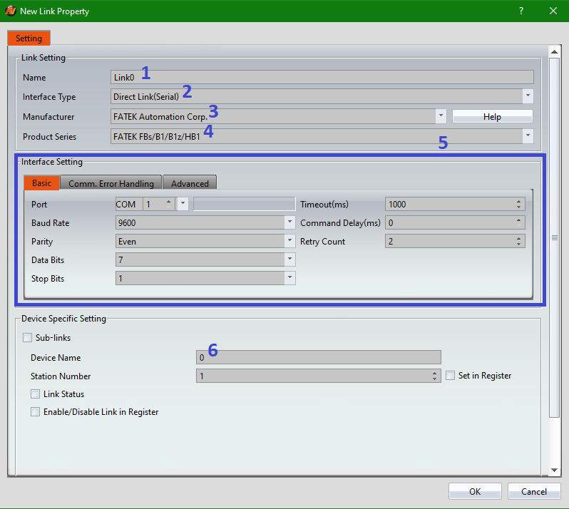
- [Name] this is just a name that will be shown in “Link” and that we can place to remember a specific configuration.
- [Interface Type] This is the interface that will be used to connect with the HMI, the main ones are serial and Ethernet.
- [Manufacturer] you must indicate who is the manufacturer of the PLC and the available alternatives depend on whether ethernet was selected or not.
- [Product Series] Here the series or model of PLC that will be used is indicated. The alternatives shown depend on the selected manufacturer.
- [Interface Setting] is where the communication to be used is configured, and it depends on the settings in points 1, 2, 3, and 4.
- [Device Name] This is a name with which we will be calling the communication created, preferably it should be a short and symbolic name because we will be using it frequently.
In this case we will use a Fatek PLC through Serial communication using its same communication protocol so we leave the communication that comes by default and we’ll only change the “Device Name” for PLC1.
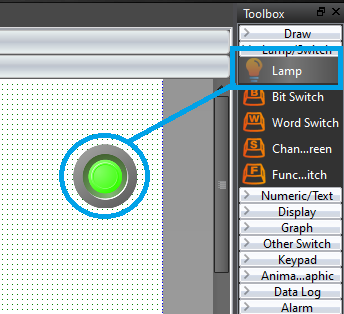
Once we have finished configuring our communication, we must click on “OK”, Alright! Now we are ready to start using our communication. For example, if we wanted to see the status of a digital input from our Fatek PLC, we need to locate the “Objects” section in the upper right part of the “Design” tab, there the first figure shaped like a lightbulb is the “Lamp” or simple indicator, just click on it and then click on our workspace to add the lamp:
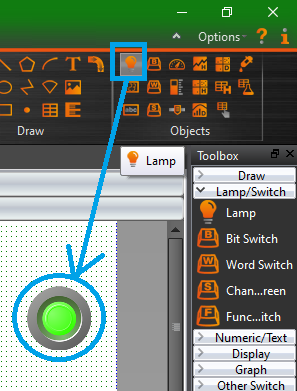
Another alternative is to go to the “Toolbox”, this by default is on the right side, if it isn’t shown there or you can’t find it, you can activate and deactivate it in “View” -> “Toolbox”, now that we located the “Toolbox” we click on “Lamp/Switch”, in this case it is necessary to click and drag the figure to the workspace, however, the result is the same to the previous procedure:
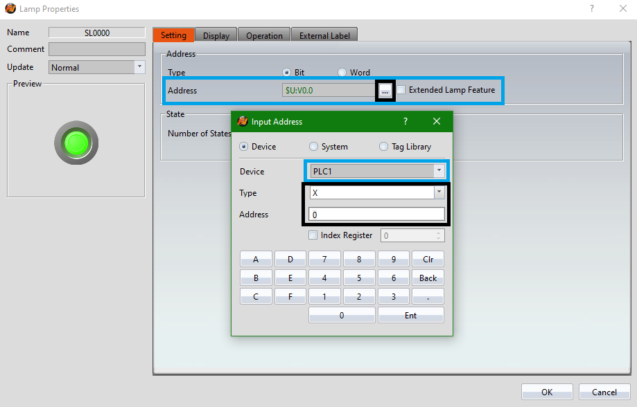
Very well! Now let’s move on to where we left off regarding communication, almost with all the “Objects” the procedure is the same, we just have to double click on the object already in our workspace, this will display a configuration window, we must look for the space where it says “Address”, in a small box we will see an address that has that object defined, near to the right edge of the box there’s a small button with “…” (three points), this is where we’ll use the communication already created, clicking it will display a small subwindow. In “Device” we must select our created communication, then in “Type” and “Address” it normally changes depending on the communication, in this case, being a Fatek PLC, the digital inputs are represented with an “X” and the first input is referenced with the number “0”, once this has been defined, all you have to do is press “Ent” and then “OK”, ready now you can test your communication in the simulator or directly with an HMI and a PLC:
Now let’s see an example of how to perform Serial and Ethernet communication with a Fatek PLC to see some integer type variables in the following video:
If you are working on any application that we can help you with or have any questions, please let us know. We offer free technical support to help you choose the best equipment for your application.
Contact us
Email: sales@logicbus.com and support@logicbus.com
Whatsapp: +1 619-600-1015
Online chat: Start conversation